PLAYER Schematics
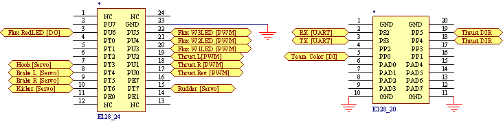
Pinouts for the E128 on the player
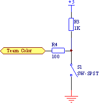 Team color selection switch.
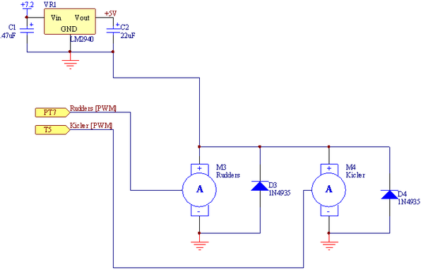 Servo power and control signals for the rudder servos and kicker servo.
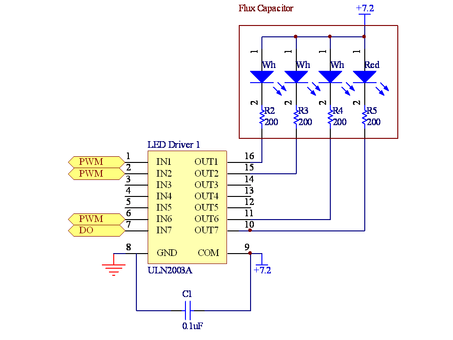 Control signals and power to the flux capacitor (our energy meter)
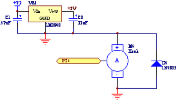 Servo power and control signal for the hook attached to the roof (low power indicator).
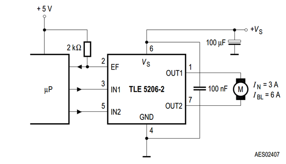 TLE5206 H-bridge motor driver used for thruster fans.
COACH Schematics
The COACH side included a 'C32, a PIC16F690, and a XBee24 radio module. The 'C32 handled all of the COACH I/O, while the PIC communicated via UART with the XBee24 radio module. The 'C32 forwarded information to the PIC via SPI. The SPI network consisted of one master ('C32) and two slaves (the radio PIC and an output shift register that controlled the energy status and pairing LEDs).
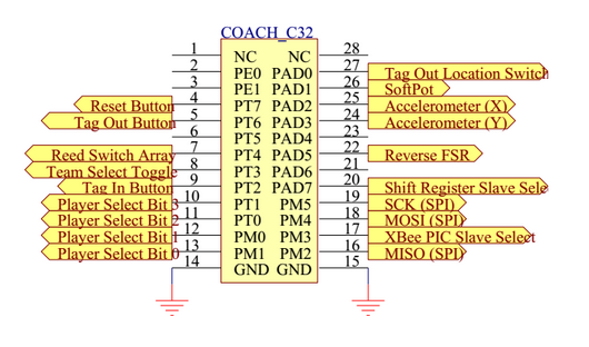
COACH 'C32 pinout.
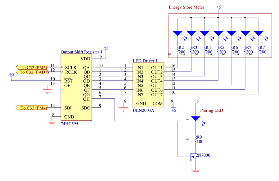
Output shift register and Darlington driver for Energy Store Meter and Pairing LEDs.
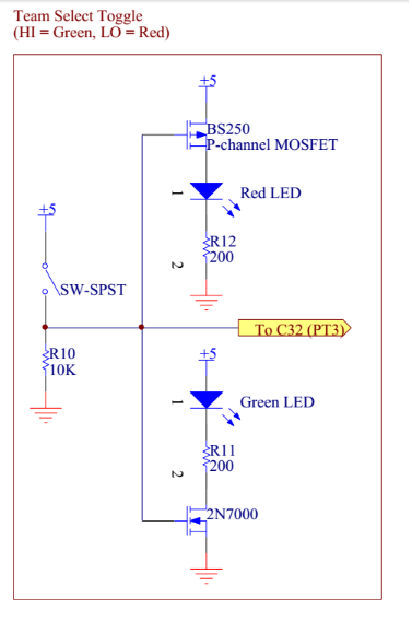
Team select toggle.
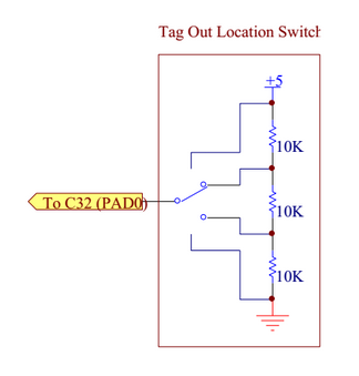
Tag out location switch. A four-position rotary switch allows the circuit to output four distinct voltages depending upon where it taps into the voltage divider. The output is fed to an A/D pin and depending upon the value read, a tag-out location of 0-3 is assigned in software.
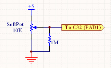
SoftPot linear potentiometer. A 1M pull-down resistor is used since the wiper is floating when the SoftPot is not engaged.
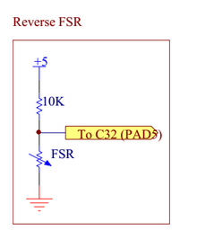
A FSR was used to send reverse commands. It was essentially configured in "button mode" -- when pressed hard enough to trigger a logical low, we sent a full reverse command to our paired PLAYER.
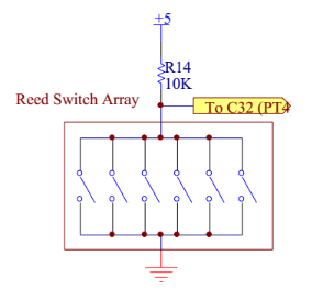
An array of magnetically-triggered reed switches was used to signal kick commands. Six switches were wired in parallel, both to make it easier to trigger and to vaguely resemble guitar strings.
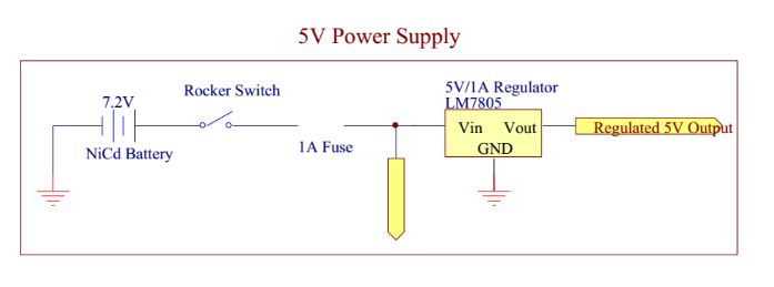
The COACH was powered by a 7.2V NiCd battery. This was fed directly into the 'C32 -- which has its own on-board 5V regulator -- as well as a LM7805 low-dropout 5V regulator which we used to power all of our peripheral electronics.
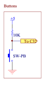
All buttons on the COACH (Reset, Tag In, Tag Out) were active low, configured as shown.
We also used a 3-axis accelerometer module from Modern Device. We mounted it in the guitar such that the Z-axis was perpendicular to gravity and connected the X- and Y- accelerometer outputs to A/D pins. After calibrating on start-up, we were able to detect angular deviations from an equilibrium position and translated those angles into appropriate turning values that we then sent to our PLAYER. By using both the X and Y values of the accelerometer, we were able to make the angle detection more robust to calibration location and noise.
COACH Design Calculations
We decided to run our COACH off of a single 7.2V 1800 mAh NiCd battery. If we want to run untethered for 8 hours before recharging (as was called for in the project description), we need to limit our continuous current consumption to (1800 mAh / 8h) = 225 mA.
CURRENT SOURCES:
CURRENT SOURCES:
- XBee - 50 mA (peak, when transmitting)
- 74HC595 - <<1 mA
- ULN2003 - <1.25 mA
- Energy Store LEDs - 87.5 mA ( 7*(5V-2.5V)/200 )
- Pair LED - 20 mA ( (5V-3V)/100 )
- Team Color LED - 12.5 mA ( (5V-2.5V)/200 )
- Accelerometer - 0.4 mA
- Radio PIC - <1 mA
- 'C32 - 40 mA (continuous)
- LM7805 - <10 mA (8 mA quiescent current + ~0.5-1 mA under load)
- total current from all other devices (buttons, switches, etc.) averages out to less than 1 mA
